Piccoboard Troubleshooting Guide
(See also Piccoboard identification and Piccoboard Gyro Issues)At this time, I am prepared to repair output FET failures, Schotky diode failures, some gyro failures and most foil damage. I will also sell the gyro element by itself (US$25 each plus US$3 for worldwide shipping) to anyone adventuresome enough to attempt gyro replacement.
Find the heading that best describes your failure mode, answer the questions, and hopefully we can narrow the failure down and determine if it is repairable.
One motor runs normally, one does not
Make sure that you do not have a transmitter problem first!
Try another motor. If a known good motor still does not run, this is almost certainly an output FET and/or Schotky failure.
Likely cause: FET failure. Repairable ($40) Return to main Piccoboard repair page
Both motors do NOT run, LED indicates successful initialization
Again, verify that you do not have a transmitter problem!
Try a known good motor on each output. If known good motors do not run, this is probably damaged output FETs, although it is possible that there is other damage since it less likely that both output FETs have failed at the same time.
Likely cause: FET failure. Repairable ($40) Return to main Piccoboard repair page
Both motors do NOT run, LED does NOT indicate successful initialization
This could be due to gyro failure, receiver failure, transmitter failure, battery failure, wiring failure.... etc. If you have access to a voltmeter, measure the voltage at the battery input to the Piccoboard. You should have at least 7.7V. Try another receiver if you have access to one. Try the transmitter with another model if possible. If all external causes check out, the most likely failure is the gyro.
Repairable ($55) Return to main Piccoboard repair page or jump to the gyro replacement section
Both motors respond to transmitter, LED indicates successful initialization, no gyro action
This is a gyro failure.
Repairable ($55) Return to main Piccoboard repair page or jump to the gyro replacement section
One or both motors run full or part throttle as soon as power is connected
Likely cause: FET failure. Repairable ($40) Return to main Piccoboard repair page
Gyro Troubleshooting
If you have a voltmeter, you can confirm a defective gyro by measuring the four gyro pins with the meter (-) lead connected to the Piccoboard battery (-) input. For this measurement, the motors do not have to be plugged in but the Piccoboard does have to be plugged into the receiver and the transmitter must be on with the throttle stick at zero throttle. Refer to the following photo....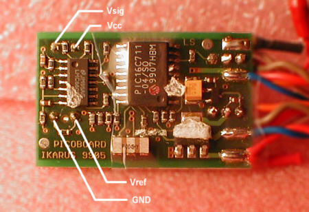
The "GND" pin should measure 0V. The Vcc pin may measure either 3V or 5V depending on Piccoboard model (read the Gyro Page.... this may be part of the problem). If your gyro is marked "5AB1" or "5AB0" it is an older 5V gyro and the Vsig and Vref pins must be at the same voltage and should measure approximately 2.4V. If your gyro is marked "3AB1" or 3AB0" it is a newer 3V gyro and the Vsig and Vref pins must be at the same voltage and should measure approximately 1.3V. If the voltages at the Vsig and Vref pins are not approximately correct based on the gyro marking OR if they are not within about 100 mV of each other, the gyro is defective and your Piccoboard may not initialize. Note that I have discovered that the Piccoboard apparently does not actually use the Vref voltage. If it is not correct, that is an indication of an internal gyro problem although the gyro MAY function correctly as long as the Vsig is close to correct.
Gyro removal and replacement
This section is provided for those of you determined to do it yourself. Removing the gyro is not easy and is best left to someone with expert soldering skills and experience working on miniature circuit boards. If you are not careful, you can lift one or more foil traces from the board and make the board difficult or impossible to repair.In addition, replacing the gyro on a standard Piccoboard without modifying the board to lower the Vcc to less than 4V may cause subsequent gyro failure. Unfortunately, the modification involves some very delicate soldering and removal and replacement of VERY small surface mount components. I do not recommend that anyone attempt it unless you are totally comfortable with desoldering and soldering 1/16W (1.6mm long) SMT resistors and other related SMT rework operations.
If this does not scare you, here are a couple tips on gyro replacement. It does not cover the other rework operations required if your board supplies 5V to the gyro.
If you have access to a desoldering station, this is the best way to remove a gyro. But if you are VERY careful, you can do it without one. Heat one pin at a time and gently lever the gyro out one pin at a time. Make sure you do not damage any components on the board, and be VERY cautious about heating any one pin too long or too hot. Getting started is the most difficult part because you will not be able to lift that first pin very far.
With the gyro removed, add some solder to the four pads so that there is a very slight mound of solder at each pad. This will assist in soldering the new CG-L43 gyro in place. Look at the new CG-L43 gyro. It will have a small plastic nub projecting down on the bottom of the gyro. The gyro will mount with this nub closest to the edge of the board. Once it is located, it can be cut off with a sharp pair of small side cutters if desired.
Bend all four pins under the gyro at about 45 degrees and tin them gently. Orient the gyro on edge at about 45 degrees with the two pins closest the pots touching the solder pads. With a small thin soldering iron tip, reach in and heat the pins and pads and solder the two pins. Now fold the gyro down against the board and solder the remaining two pins and you are done. It isn't hard but it requires some finesse.
Power up and test.