Finally! A viable shutter speed control for the PC23C. This information is posted here out of convenience but is in reality mostly the brilliant work of Charles Allison, who scoped out the Sony chipset data sheets and discovered that the shutter speed can be controlled by manipulating a voltage that is readily available on the camera board.
For the latest from Charles, see his web site. There you will find a zip file for his latest shutter speed modifications. He also has a downloadable program that works with the Snappy frame grabber to snap a sequence of images.
What follows here are earlier versions of the shutter speed modifications, including a very simple one that only involves a few resistors and a couple pushbuttons.
While there are several resistors and two or three switches required to achieve manual shutter speed control, these can be conveniently located outboard from the camera using the existing IRIS control connector. The signals necessary are the control voltage, 12V and ground. 12V and ground are already available on the iris connector (you did save the mating half, didn't you?). And by moving one wire inside the camera, the IRIS control signal becomes the shutter speed control voltage.
To modify the camera (tried on version 1 only.... NOT tested on version 2 but it may work), locate the blue wire that goes to a pad next to where the yellow wire was (still is if you have not done my video AGC mod). Now locate a strip of six pads along the side of the board. One will be square and the rest round. The square pad is the #1 pad. Move the blue wire from where it is to the #6 pad of the strip of pads and the camera end of the modification is complete.
Now, all that is needed to achieve manual shutter speed control is to build one of the following suggested circuits below and plug it into the IRIS connector and you're done.
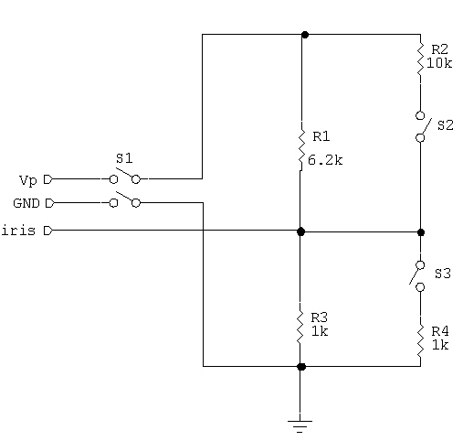
Version 1 from Charles Allison
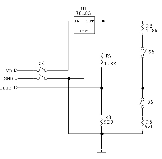
Version 2 from Charles Allison (un-tested as of now)
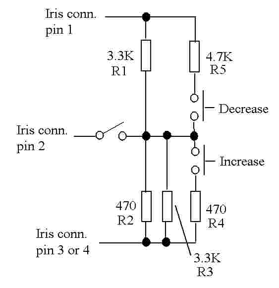
Version 1 from Paul Goelz, using common (ie., available at Radio Shack) resistor values (tested on one camera)
The toggle switch in each schematic is to enable or disable manual shutter speed control. However, it has another interesting effect.... if it is in the automatic (open) position, and then is placed in the manual (closed) position, the shutter speed will stay at its present value... locked in until the switch is placed back in automatic or one of the up/down pushbuttons are pressed.
Note that it is strongly recommended that you perform the video gain mod at this time if you have not done so already. Leaving the video gain in the un-modified condition will result in the video AGC action boosting the video levels to the point of clipping on small bright objects regardless of shutter speed settings. Performing the video gain mod will allow full manual control of exposure (and resulting video level) by varying the shutter speed.
I am also working on a variation to the video gain mod that will still leave the video gain in manual but will not reduce the overall gain as far. I am also looking into making the video AGC peak sensing rather than average sensing, which should correct the exposure problem for good, retaining the convenience of automatic exposure control (essential for those of us who operate our scopes remotely).
A final note. These circuits are still a bit experimental, and the resistor values might have to be adjusted a bit depending on your particular camera. The injected voltage from the outboard voltage divider overpowers an output from the 1310 chip, and this can possibly have an unpredictable effect on the voltage divider output. No damage will be done, but if you find that the shutter speed cannot be adjusted up or down, or that it goes all the way in one direction, adjusting one if the two resistors in the divider to bring the voltage back to the vicinity of 1.6V should take care of it. Charles came up with two designs and I came up with a third. The only real difference is that Charles' circuit uses a couple 1% resistor values and I tried to stick with common values available at good ol' Radio Shack (hence the two parallel resistors in my version). I built my circuit on a scrap of perf board and shrink wrapped it. It connects to the iris connector with a 5' length of 3 conductor (2 conductors and a shield) mic cable. The shield may be un-necessary.
Just for grins, I also built an experimental version that used a 5K pot to ground and a 4.7K resistor to 12V, with a 2.2K resistor from the wiper to the control pin, and no pushbuttons. That version gave me a measure of shutter speed offset in the center of rotation and also retained some automatic control near the center of rotation. Turning the pot far enough in either direction ramped the shutter speed up or down.
And again, thanks to Charles Allison for the excellent work. Well done, Charles!!